A Guide to Electromagnetic Flow Meters in Industry
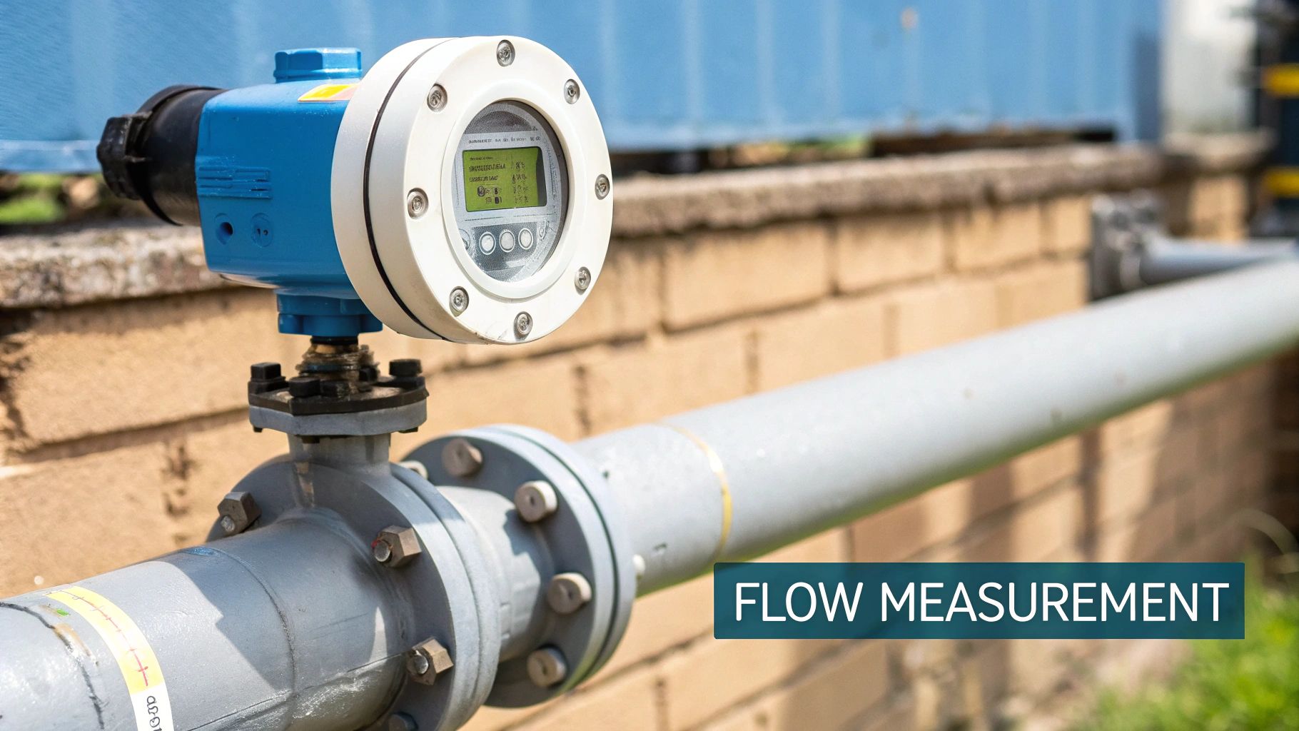
Electromagnetic flow meters, often called magmeters , are specialist devices built for one key job: measuring the flow rate of conductive liquids inside a pipe. Their whole operation hinges on a fundamental physics principle known as Faraday's Law of Electromagnetic Induction , which cleverly links electricity and magnetism to the motion of a fluid.
You can think of it as a small, self-contained generator where the flowing liquid itself helps to create a measurable electrical signal.
Unlocking Precision in Modern Energy Systems
In the world of advanced energy, getting your measurements right is not just a nice-to-have; it is a must. Electromagnetic flow meters give us a highly accurate and reliable way to monitor conductive fluids, solving many of the headaches that older, mechanical meters just cannot handle.
The real beauty of their design is the unobstructed path for the liquid. There are no moving parts to wear out, jam or get clogged up.
This non-intrusive approach is vital in systems where efficiency and uptime are everything. From managing coolant flow in grid-scale batteries to ensuring the correct liquid management in combined on-site renewables, magmeters deliver consistent, trustworthy performance. Because they do not cause any drop in pressure, they also boost overall system efficiency—a key pillar of effective business energy management.
The Growing Demand for Accurate Measurement
It is no surprise that magmeters are becoming more common, especially in sectors with tight regulations and complex requirements. In the UK, for instance, huge pressure on utilities to reduce water wastage has driven major investment in modern metering but the technology is now essential in distributed energy systems.
This trend is also clear in the energy sector, where precise control is non-negotiable. For example:
- Rapid EV Charging: You need to measure coolant flow accurately to handle the intense heat generated during a fast charge. This protects both the charger and the vehicle’s battery.
- Grid-Scale Batteries: These massive systems depend on liquid cooling to stay at the right temperature. Magmeters are there to make sure the thermal management systems are working perfectly, a critical factor for both safety and battery lifespan.
- Combined On-site Renewables: In hybrid systems that combine solar with grid-scale batteries, fluid-based heat exchangers often need close monitoring to squeeze out every bit of efficiency and ensure optimal performance.
At their core, electromagnetic flow meters translate the physical movement of a conductive liquid directly into a clean, linear electrical signal. This direct relationship between velocity and voltage is what makes them so accurate and dependable for critical applications.
Integration into Smart Energy Networks
As our energy systems get smarter and more connected, the data from magmeters becomes even more valuable. These devices are increasingly being integrated into larger smart infrastructure setups. To get a better sense of how devices like these fit into the bigger picture, it is worth understanding the role of IoT in building automation systems.
This connectivity allows for real-time monitoring and control, which is essential for managing distributed energy resources like EV charging and batteries. It is particularly important for handling EV charging from constrained grid connections, where intelligent load management is key.
How Faraday's Law Unlocks Precise Flow Measurement
At the core of every electromagnetic flow meter is a beautifully simple physics principle: Faraday's Law of Induction . This law describes the elegant link between magnetism and electricity. To put it simply, when a conductive material moves through a magnetic field, it generates a voltage.
This is not just some abstract concept from a textbook; it is the very mechanism that allows these meters, often called magmeters, to measure fluid movement with incredible precision. Think of it as a tiny, frictionless generator. But instead of spinning turbines, the moving liquid itself acts as the conductor, creating a tiny but measurable electrical signal as it flows past.
The faster the fluid is moving, the stronger the voltage signal it creates. This direct, linear relationship is what makes electromagnetic flow meters so dependable and accurate for mission-critical jobs in distributed energy management.
Generating The Signal From Liquid Flow
So, how does this actually happen inside a pipe? An electromagnetic flow meter is built with a pair of magnetic coils and at least two electrodes. When you power the meter up, these coils create a steady, controlled magnetic field that cuts right across the entire pipe.
As a conductive fluid—like the coolant essential for a grid-scale battery energy storage system—flows through this field, it acts just like the conductor in Faraday's Law. A voltage is induced directly within the fluid and its strength is perfectly proportional to how fast the liquid is moving.
The electrodes, positioned on opposite sides of the pipe and in direct contact with the liquid, are there to sense this. They pick up the tiny voltage signal, which the meter’s transmitter then processes and converts into an exact, usable flow rate.
The process is quite straightforward when you see it laid out.
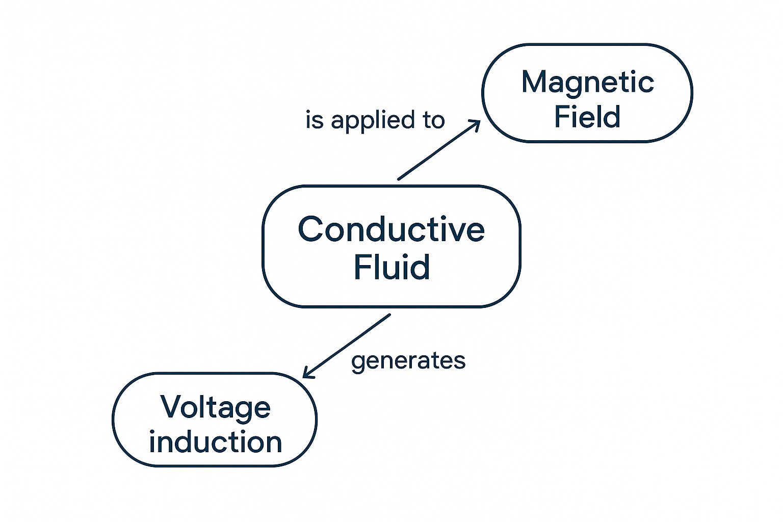
As the visual shows, the magnetic field is the catalyst, the moving liquid is the conductor and the induced voltage is the direct, measurable result.
Applications In Advanced Energy Systems
This operating principle is a perfect fit for the tough demands of modern energy infrastructure. Unlike old-school mechanical meters, magmeters have no moving parts to wear out, break down or get in the way of the flow. This makes them ideal for managing fluids where safety and efficiency are non-negotiable.
Just look at these real-world examples:
- Rapid EV Charging: The huge amount of power needed for rapid charging generates a lot of heat. Magmeters are used to monitor the flow of liquid coolant with pinpoint accuracy, ensuring the entire system stays within safe operating temperatures and preventing damage to expensive chargers and vehicle batteries.
- Grid-Scale Batteries: Large battery farms depend on complex thermal management to stay healthy. Electromagnetic flow meters provide the vital data on coolant circulation, helping operators maintain optimal battery performance and squeeze every bit of life out of these critical grid assets.
- Mobile EV Charging: For mobile or temporary charging setups, which often have to work with constrained grid connections, every drop of energy counts. Accurate flow measurement helps optimise the cooling and energy transfer, guaranteeing reliable performance no matter where the charger is deployed.
Faraday's Law provides a direct, linear and highly repeatable method for measurement. Because the induced voltage is only dependent on the fluid's velocity, factors like fluid density, viscosity and temperature have virtually no effect on the accuracy of the reading.
This inherent robustness is what makes electromagnetic flow meters a cornerstone technology in distributed energy systems. The data they produce is clean, reliable and ready to be fed into smart control systems. As our energy networks get more complex, the role of AI and big data in revolutionising energy management is only growing and precise inputs from sensors like magmeters are absolutely essential. By providing trustworthy flow data, these meters enable smarter, more responsive and ultimately more efficient energy use right across the board.
Breaking Down the Core Components of a Magmeter
To really get a feel for how electromagnetic flow meters deliver such reliable performance, it helps to look under the bonnet. While they look simple from the outside, each internal component has a specific, vital role in turning fluid movement into precise data. These parts work together seamlessly, creating a robust system that is perfectly suited for demanding applications like EV charging and grid-scale batteries.
At its heart, a magmeter is made up of four essential elements: the flow tube, magnetic coils, sensing electrodes and a transmitter. Each one is engineered to contribute to the final measurement, ensuring accuracy even in the challenging environments found in EV charging infrastructure from constrained grid connections and grid-scale battery systems.
Let's take a closer look at what each component does.
The Flow Tube and Liner
The flow tube is the main body of the meter, essentially becoming a section of the pipeline itself. It is built from a non-magnetic material to avoid interfering with the measurement process. Critically, the inside of this tube is coated with a non-conductive liner .
This liner is more important than it looks, serving two key purposes. First, it electrically insulates the flow tube from the conductive liquid. This stops the voltage signal from short-circuiting through the metal pipe wall, which would make an accurate measurement impossible. Second, it acts as a barrier against corrosion and abrasion, protecting the meter from aggressive fluids.
The choice of liner material is a critical decision and depends entirely on the application. For instance, managing the coolant in a rapid EV charging station or a grid-scale battery requires a material that can handle specific chemical properties and temperature ranges without degrading.
Magnetic Coils: The Field Generators
Mounted on the outside of the flow tube are powerful magnetic coils . When energised, these coils generate a consistent and precisely controlled magnetic field that penetrates the flow tube and the liquid flowing through it. The stability of this field is absolutely essential for an accurate measurement.
Modern magmeters use a pulsed DC voltage to energise the coils. This clever technique creates a stable magnetic field while also helping to cancel out electrical "noise" from the measurement signal—a common problem in industrial settings buzzing with other equipment. This is particularly important when deploying mobile EV charging units near sources of potential interference.
Electrodes: The Signal Sensors
Positioned on opposite sides of the flow tube, flush with the inner liner, you will find the electrodes . These small sensors are in direct contact with the flowing fluid. Their job is to detect the tiny voltage induced by the liquid's movement through the magnetic field.
Because they touch the process fluid, the electrode material must be carefully chosen to resist corrosion and avoid "fouling," where a non-conductive layer builds up and blocks the signal. Just like the liner, the material choice depends on the job, ranging from stainless steel for clean water to more exotic alloys like Hastelloy C for aggressive chemicals.
The voltage picked up by the electrodes is incredibly small, often just a few millivolts. The ability of the system to accurately capture this faint signal amidst potential electrical noise is a real testament to the sophisticated engineering behind modern magmeters.
Getting the material selection right for both the liner and electrodes is fundamental to a magmeter's long-term performance and reliability. The wrong choice can lead to premature failure, inaccurate readings and costly downtime.
Comparing Common Liner and Electrode Materials
This table breaks down some of the most common materials, giving you an idea of where each one shines.
| Material | Chemical Resistance | Max Temperature | Best Suited For |
|---|---|---|---|
| Hard Rubber | Good for water, waste, and slurries | ~80°C | General-purpose water and wastewater applications. |
| PTFE / PFA | Excellent for most chemicals, acids, and bases | ~150°C (PTFE), ~180°C (PFA) | Aggressive chemical processing, high-purity applications. |
| Polyurethane (PU) | Excellent abrasion resistance | ~60°C | Abrasive slurries like sand, cement, or mining tailings. |
| Stainless Steel 316L | Good for water, mild chemicals | ~150°C | Water, wastewater, food and beverage, and less corrosive fluids. |
| Hastelloy C | Excellent for strong acids and corrosive media | >200°C | Highly corrosive chemical services (e.g., chlorine, sulphuric acid). |
| Tantalum | Superb resistance to aggressive acids | >200°C | Very specific, highly corrosive environments where others fail. |
Choosing the right combination ensures your meter not only provides accurate data but also stands the test of time in its specific operational environment.
The Transmitter: The Brains of the Operation
The final key component is the transmitter . This electronic unit is the "brain" of the whole setup. It takes the very low-level voltage signal from the electrodes and converts it into a stable, usable output that a control system can understand.
Here is a breakdown of what it does:
- Signal Amplification: It boosts the tiny voltage from the electrodes into a stronger, more robust signal.
- Noise Filtering: It filters out any electrical interference to ensure the final reading is based purely on the fluid's flow, not background noise.
- Conversion to Flow Rate: Using the meter’s unique calibration factor, it translates the voltage into a standard flow measurement, such as litres per minute or cubic metres per hour.
- Output Signal: It provides the final data in a format ready for control systems, like a 4-20mA analogue signal or a digital output for integration into distributed energy networks.
Together, these components create a highly accurate and reliable measurement system with no moving parts to wear out or break down. This makes it the ideal choice for monitoring critical fluids in everything from grid-scale batteries combined with on-site renewables to mobile EV charging units.
Here is why so many are making the switch to electromagnetic flow meters over traditional methods like turbine or orifice plates. The answer is surprisingly simple: they measure flow without getting in the way and have no moving parts.
That single design philosophy unlocks a cascade of benefits. With no gears, bearings or rotors to wear down, magmeters deliver exceptional reliability and drastically slash maintenance needs. This is a game-changer for critical infrastructure like rapid EV charging stations or grid-scale batteries, where downtime simply is not an option.
Unmatched Reliability and Low Maintenance
Older mechanical meters are a constant headache, especially when dealing with fluids that are not perfectly clean. A turbine meter in a wastewater application, for instance, can get clogged or damaged by debris in no time, leading to faulty readings and expensive repairs.
Electromagnetic flow meters , on the other hand, offer a clear, unobstructed pipe for the fluid. This non-intrusive design makes them practically immune to the blockages and mechanical failures that plague older technologies.
The lack of moving components means magmeters are often a 'fit and forget' solution. This translates directly to lower running costs and greater peace of mind, especially for remote or hard-to-reach installations common in distributed energy networks.
This durability is a massive advantage when managing the abrasive slurries or corrosive coolants found in modern energy systems like EV charging and batteries. The smooth liner and stationary electrodes are built tough, ready to withstand harsh conditions and ensure a long, reliable service life.
Superior Energy Efficiency and Accuracy
Another huge win is the elimination of pressure loss. Orifice plates and similar meters work by creating a deliberate bottleneck in the pipe. This forces the pumps to work harder, burning through a significant amount of energy just to maintain the target flow rate.
Because a magmeter presents no such obstacle, the pressure drop is virtually zero. This leads to real energy savings that boost the overall efficiency of the entire system. For large-scale operations, like managing coolant flow in a grid-scale battery energy storage system (BESS), these savings can be substantial.
On top of that, their accuracy across a wide range of flow rates is exceptional. While a mechanical meter often loses precision at very low speeds, a magmeter maintains its accuracy. This makes it perfect for systems with fluctuating demand, such as:
- Mobile EV Charging Units: Where power output and coolant flow need to adapt based on a constrained grid connection.
- Combined On-site Renewables: Managing heat transfer fluids where energy generation rises and falls with the sun or wind, requiring precise coordination with battery storage.
Thriving in a Growing Market
The shift towards these advanced meters is clear from market trends across Europe. The UK’s flow meter market is expanding fast, driven by industrial automation and tougher environmental regulations. In 2022, the European market was valued at around USD 6.875 billion , with electromagnetic meters taking a significant share due to their precision.
This market is set to grow at a CAGR of 6% between 2023 and 2030 , spurred on by major investments in clean technologies and distributed energy infrastructure that all rely on accurate fluid monitoring. With UK manufacturers increasingly adding digital capabilities, the sector is on track to help the European market reach nearly USD 11.7 billion by 2030 . You can find out more about the trends in the European flow meter market and how the UK is contributing.
How to Select the Right Magmeter for Your Application
Choosing the correct electromagnetic flow meter is not a minor detail; it is a critical decision. Getting it wrong can lead to dodgy data, disruptions to your operations and even premature equipment failure. This guide will walk you through the key things to consider, making sure you specify a magmeter that fits your needs perfectly, especially for demanding distributed energy applications.
The whole process starts with properly understanding the fluid you need to measure. Whether it is the coolant circulating in a grid-scale battery system or the liquids managed in combined on-site renewable energy processes, every fluid has unique properties that will dictate the meter’s final specification.
Analyse Your Fluid Properties
First things first, you need to get to grips with the characteristics of your process fluid. The success of any magmeter hangs on the liquid being conductive enough to generate a signal the meter can actually read.
There are a few key attributes you will need to evaluate:
- Conductivity: This is the absolute deal-breaker. Most magmeters need a minimum conductivity of around 5 µS/cm (microsiemens per centimetre). You must confirm your fluid’s conductivity and check it against the manufacturer’s specifications.
- Temperature and Pressure: What is the normal operating range and what are the potential extremes? The meter’s materials have to be tough enough to handle these conditions without degrading or becoming a safety risk.
- Corrosiveness and Abrasion: Think about the chemical makeup of your fluid. Is it corrosive, like some battery coolants, or abrasive, like a slurry? This will have a huge say in your choice of liner and electrode materials.
Making a careful, informed decision here is the best way to prevent compatibility issues that could lead to meter failure down the line.
Matching Materials to the Application
Once you have a clear picture of your fluid, you can pick the right materials for the parts that will be in direct contact with it. This choice is fundamental to the longevity and accuracy of your electromagnetic flow meter.
The liner , which is the coating on the inside of the flow tube, has to be chemically resistant to your fluid and provide electrical insulation. For the aggressive chemicals often found in energy systems, PTFE is a popular choice, whereas hard rubber might be perfectly fine for general water applications.
In the same way, the electrodes that sense the voltage cannot corrode or react with the fluid. Materials can range from standard stainless steel for clean liquids to specialised alloys like Hastelloy C for highly corrosive stuff. For mobile EV charging systems where the coolants might vary, picking robust materials is a key consideration.
Choosing the right liner and electrode combination is not just about chemical compatibility; it is about guaranteeing the long-term reliability of your entire measurement system. A mismatch can lead to inaccurate readings and costly maintenance.
Sizing and Installation Environment
Sizing a meter correctly is about more than just matching the existing pipe diameter. The aim is usually to achieve a flow velocity between 2 to 3 metres per second at maximum flow. This sweet spot ensures a strong, stable signal for the transmitter to process.
For abrasive fluids, it is often smarter to use a larger meter to slow the velocity down and minimise wear and tear on the liner. On the other hand, in gravity-fed systems, a larger size might be needed to avoid creating a bottleneck that restricts the flow.
Finally, think about the physical environment. Will the meter be installed somewhere that requires specific safety ratings, like an ATEX certification for hazardous areas? You also need to consider how it will connect to your wider system.
Does your setup just need a simple 4-20mA analogue signal or do you need a digital output like RS-485 to integrate it into a distributed energy management system? Answering these questions ensures the meter you choose will slot smoothly into your operations from day one, whether it is for a fixed rapid EV charging hub or a complex grid-scale battery installation.
Installation Best Practices to Ensure Accuracy
Poor installation is one of the most common reasons for measurement errors. By following a few key best practices, you can avoid frustrating issues and get the most out of your equipment from day one. These steps are particularly important in complex distributed energy systems like EV charging hubs or grid-scale battery installations, where precise coolant flow is non-negotiable.
Ensuring a Stable Flow Profile
The single most critical factor for accuracy is ensuring a smooth, undisturbed flow profile as the liquid enters the meter. Any turbulence, swirling or an incompletely filled pipe can seriously distort the measurement signal and lead to completely wrong readings.
To prevent this, you absolutely must provide sufficient straight pipe runs both before and after the meter. A solid rule of thumb is to have at least five pipe diameters of straight pipe upstream (before the meter) and two pipe diameters downstream (after the meter). This gives any disturbances from valves, pumps or bends a chance to settle down, creating a stable, even profile for the measurement.
An electromagnetic flow meter measures the average velocity across the pipe's diameter. If the flow is turbulent or uneven, this average will be skewed, leading to significant errors in the final flow rate calculation.
Proper Grounding and Pipe Conditions
Electromagnetic flow meters work by detecting an incredibly small voltage signal. This makes them highly susceptible to electrical "noise" from nearby motors, pumps or variable frequency drives, which can easily corrupt the reading. Proper grounding is therefore essential to provide a clean signal path.
Always follow the manufacturer's instructions for grounding, using grounding rings or straps to ensure the meter, fluid and connecting pipes are all at the same electrical potential. It is a vital step for filtering out interference and maintaining signal integrity.
Furthermore, the pipe must always remain completely full of liquid during operation. An empty or partially filled pipe will cause the meter to read incorrectly, plain and simple. Installing the meter in a vertical pipe with an upward flow or in a low point of a horizontal run can help ensure it stays full. This is a key consideration for reliable grid energy management, where consistent data is essential for system optimisation.
Routine Maintenance and Troubleshooting
Thanks to their lack of moving parts, electromagnetic flow meters require very little maintenance but they are not entirely "fit and forget." Regular checks can prevent minor issues from turning into major problems down the line.
Here are a few common issues to watch for:
- Electrode Fouling: A build-up of material on the electrodes can insulate them from the fluid, leading to weak or zero readings. This is quite common in applications with a high solids content.
- Signal Interference: If new electrical equipment is installed near the meter, it could introduce noise. Verifying the grounding is always a good first step in troubleshooting.
- Liner Damage: In abrasive applications, it is wise to periodically inspect the liner for wear and tear to prevent leaks or outright meter failure.
Simple, routine inspections and prompt troubleshooting will help maximise the lifespan and accuracy of your electromagnetic flow meters. This ensures they continue to support critical operations, whether in rapid EV charging or distributed energy systems.
Got Questions About Electromagnetic Flow Meters?
To wrap things up, let's tackle some of the most common questions people have when working with magmeters. Getting these details right is crucial for avoiding pitfalls, especially in demanding applications like EV charging coolant systems or grid-scale battery management.
A lot of confusion comes down to what these meters can and cannot handle. The key is to remember how they actually work.
Can Magmeters Measure Non-Conductive Fluids Like Oils or Gases?
In a word, no. The entire operating principle hinges on Faraday's Law, which only works if the fluid passing through is electrically conductive. Without conductivity, there is no voltage to generate and therefore nothing to measure.
This means fluids like oils, hydrocarbons and even deionised water are invisible to a magmeter. The same goes for any type of gas. For those jobs, you would need to look at a completely different technology, like an ultrasonic or Coriolis flow meter.
What Is the Minimum Fluid Conductivity You Need?
As a rule of thumb, most standard magmeters need the fluid to have a conductivity of at least 5 microsiemens per centimetre (µS/cm) . But this is not a hard and fast rule; it can definitely vary between different models and manufacturers.
It is absolutely essential to check your fluid's conductivity and make sure it is well within the meter's specified range. If you are operating right on the minimum threshold, your readings could become unreliable or drop out completely, particularly if the fluid's properties fluctuate.
You can find specialised meters designed for lower conductivity fluids, but always double-check the technical specifications before you buy.
How Does Electrode Coating Affect Performance?
Electrode coating—often called fouling—is one of the biggest culprits behind inaccurate magmeter readings. It happens when a non-conductive layer of material, like scale, grease or biofilm, builds up on the electrode surfaces.
This build-up acts as an insulator, blocking the electrodes from sensing the tiny voltage the flowing fluid generates. When that happens, the meter's readings can become erratic, drift over time or just drop to zero. This is a real risk in systems like mobile EV charging units, where coolant quality might not always be consistent.
To get around this, some meters come with built-in self-cleaning functions or clever diagnostic software. In many demanding applications, though, nothing beats a regular schedule of inspection and manual cleaning to guarantee your meter keeps delivering the accurate data your distributed energy systems depend on.
At ZPN Energy , we provide the advanced charging and energy storage solutions needed for a sustainable future. Our expertise in rapid EV charging, grid-scale batteries, and integrated energy management ensures your infrastructure is reliable and efficient. Discover how we can support your energy goals by visiting https://www.zpnenergy.com.